This site is from a past semester! The current version will be here when the new semester starts.

Modeling

This is a printer-friendly version. It omits exercises, optional topics (i.e., four-star topics), and other extra content such as learning outcomes.

Introduction

What

A model is a representation of something else.

A class diagram is a model that represents a software design.

A model provides a simpler view of a complex entity because a model captures only a selected aspect. This omission of some aspects implies models are abstractions.

A class diagram captures the structure of the software design but not the behavior.

Multiple models of the same entity may be needed to capture it fully.

In addition to a class diagram (or even multiple class diagrams), a number of other diagrams may be needed to capture various interesting aspects of the software.

How

In software development, models are useful in several ways:

a) To analyze a complex entity related to software development.

Some examples of using models for analysis:

  1. Models of the
    problem domain
    can be built to aid the understanding of the problem to be solved.
  2. When planning a software solution, models can be created to figure out how the solution is to be built. An architecture diagram is such a model.

b) To communicate information among stakeholders. Models can be used as a visual aid in discussions and documentation.

Some examples of using models to communicate:

  1. You can use an architecture diagram to explain the high-level design of the software to developers.
  2. A business analyst can use a use case diagram to explain to the customer the functionality of the system.
  3. A class diagram can be reverse-engineered from code so as to help explain the design of a component to a new developer.

c) As a blueprint for creating software. Models can be used as instructions for building software.

Some examples of using models as blueprints:

  1. A senior developer draws a class diagram to propose a design for an OOP software and passes it to a junior programmer to implement.
  2. A software tool allows users to draw UML models using its interface and the tool automatically generates the code based on the model.
Model Driven Development extra

UML Models

Unified Modeling Language (UML) is a graphical notation to describe various aspects of a software system. UML is the brainchild of three software modeling specialists James Rumbaugh, Grady Booch and Ivar Jacobson (also known as the Three Amigos). Each of them had developed their own notation for modeling software systems before joining forces to create a unified modeling language (hence, the term ‘Unified’ in UML). UML is currently the most commonly used modeling notation used in the software industry.

The following diagram uses the class diagram notation to show the different types of UML diagrams.

Modeling structures

OO Structures

An OO solution is basically a network of objects interacting with each other. Therefore, it is useful to be able to model how the relevant objects are 'networked' together inside a software i.e. how the objects are connected together.

Given below is an illustration of some objects and how they are connected together. Note: the diagram uses an ad-hoc notation.

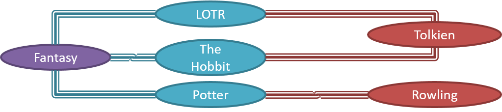
Note that these object structures within the same software can change over time.

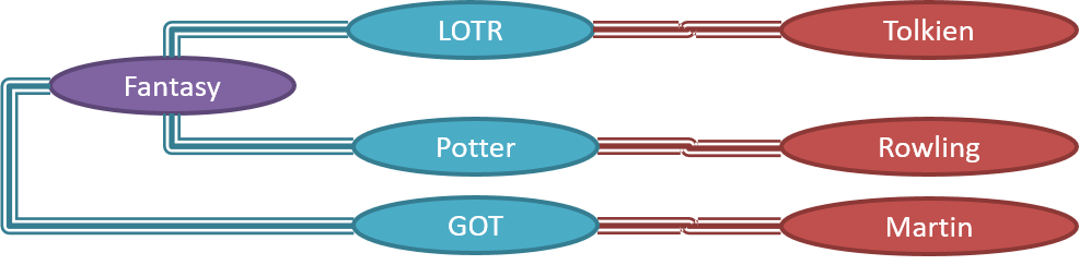
Given below is how the object structure in the previous example could have looked like at a different time.

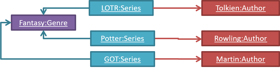
However, object structures do not change at random; they change based on a set of rules set by the designer of that software. Those rules that object structures need to follow can be illustrated as a class structure i.e. a structure that exists among the relevant classes.

Here is a class structure (drawn using an ad-hoc notation) that matches the object structures given in the previous two examples. For example, note how this class structure does not allow any connection between Genre objects and Author objects, a rule followed by the two object structures above.

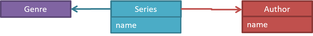
UML Object Diagrams model object structures. UML Class Diagrams model class structures.

Here is an object diagram for the above example:

And here is the class diagram for it:

Class Diagrams (Basics)

Contents related to UML diagrams in the panels given below belong to a different chapter (i.e., the chapter dedicated to UML); they have been embedded here for convenience.

Classes form the basis of class diagrams.

UML Class Diagrams → Introduction → What

UML class diagrams describe the structure (but not the behavior) of an OOP solution. These are possibly the most often used diagrams in the industry and are an indispensable tool for an OO programmer.

An example class diagram:


UML Class Diagrams → Classes → What

The basic UML notations used to represent a class:

A Table class shown in UML notation:

The equivalent code


The 'Operations' compartment and/or the 'Attributes' compartment may be omitted if such details are not important for the task at hand. Similarly, some attributes/operations can be omitted if not relevant to the purpose of the diagram. 'Attributes' always appear above the 'Operations' compartment. All operations should be in one compartment rather than each operation in a separate compartment. Same goes for attributes.

The visibility of attributes and operations is used to indicate the level of access allowed for each attribute or operation. The types of visibility and their exact meanings depend on the programming language used. Here are some common visibilities and how they are indicated in a class diagram:

  • + : public
  • - : private
  • # : protected
  • ~ : package private

How visibilities map to programming language features


Table class with visibilities shown:

The equivalent code


There is no default visibility in UML. If a class diagram does not show the visibility of a

member
, it simply means the visibility is unspecified (for reasons such as the visibility not being decided yet or it being not important to the purpose of the diagram).

Generic classes can be shown as given below. The notation format is shown on the left, followed by two examples.


Exercises:

Which classes are correct?


Draw Car class


UML Class Diagrams → Class-Level Members → What

In UML class diagrams, underlines denote class-level attributes and methods.

In the class diagram below, the totalStudents attribute and the getTotalStudents method are class-level.


Associations are the main connections among the classes in a class diagram.

OOP Associations → What

Objects in an OO solution need to be connected to each other to form a network so that they can interact with each other. Such connections between objects are called associations.

Suppose an OOP program for managing a learning management system creates an object structure to represent the related objects. In that object structure you can expect to have associations between a Course object that represents a specific course and Student objects that represent students taking that course.

Associations in an object structure can change over time.

To continue the previous example, the associations between a Course object and Student objects can change as students enroll in the course or drop the course over time.

Associations among objects can be generalized as associations between the corresponding classes too.

In our example, as some Course objects can have associations with some Student objects, you can view it as an association between the Course class and the Student class.

Implementing associations

You use instance level variables to implement associations.

In our example, the Course class can have a students variable to keeps track of students associated with a particular course.


UML Class Diagrams → Associations → What

You should use a solid line to show an association between two classes.

This example shows an association between the Admin class and the Student class:


UML Class Diagrams → Associations as Attributes

An association can be shown as an attribute instead of a line.

Association multiplicities and the default value can be shown as part of the attribute using the following notation. Both are optional.

name: type [multiplicity] = default value

The diagram below depicts a multi-player Square Game being played on a board comprising of 100 squares. Each of the squares may be occupied with any number of pieces, each belonging to a certain player.

A Piece may or may not be on a Square. Note how that association can be replaced by an isOn attribute of the Piece class. The isOn attribute can either be null or hold a reference to a Square object, matching the 0..1 multiplicity of the association it replaces. The default value is null.

The association that a Board has 100 Squares can be shown in either of these two ways:

Show each association as either an attribute or a line but not both. A line is preferred as it is easier to spot.

Diagram (a) given below shows the 'author' association between the Book class and the Person class as a line while (b) shows the same association as an attribute in the Book class. Both are correct and the two are equivalent. But (c) is not correct as it uses both a line and an attribute to show the same association.

(a)
(b)
(c)


The most basic class diagram is a bunch of classes with some solid lines among them to represent associations, such as this one.

An example class diagram showing associations between classes.

In addition, associations can show additional decorations such as association labels, association roles, multiplicity and navigability to add more information to a class diagram.

UML Class Diagrams → Associations → Labels

Association labels describe the meaning of the association. The arrow head indicates the direction in which the label is to be read.

In this example, the same association is described using two different labels.

  • Diagram on the left: Admin class is associated with Student class because an Admin object uses a Student object.
  • Diagram on the right: Admin class is associated with Student class because a Student object is used by an Admin object.

UML Class Diagrams → Associations → Roles

Association Role are used to indicate the role played by the classes in the association.

This association represents a marriage between a Man object and a Woman object. The respective roles played by objects of these two classes are husband and wife.

Note how the variable names match closely with the association roles.

class Man {
    Woman wife;
}

class Woman {
    Man husband;
}
class Man:
  def __init__(self):
    self.wife = None # a Woman object

class Woman:
   def __init__(self):
     self.husband = None # a Man object

The role of Student objects in this association is charges (i.e. Admin is in charge of students)

class Admin {
    List<Student> charges;
}
class Admin:
  def __init__(self):
    self.charges = [] # list of Student objects

Association roles are optional to show. They are particularly useful for differentiating among multiple associations between the same two classes.

In each the three associations between the Flight class and the Airport class given below, the Airport class plays a different role.


OOP Associations → Navigability

When two classes are linked by an association, it does not necessarily mean both objects taking part in an instance of the association knows about (i.e., has a reference to) each other. The concept of navigability tells us if an object taking part in association knows about the other. In other words, it tells us if we can 'navigate' from the one object to the other in a given direction -- because if the object 'knows' about the other, it has a reference to the other object, and we can use that reference to 'navigate to' (i.e., access) that other object.

Navigability can be unidirectional or bidirectional. Suppose there is an association between the classes Box and Rope, and the Box object b and the Rope object r is taking part in one instance of that association.

  • Unidirectional: If the navigability is from Box to Rope, b will have a reference to r but r will not have a reference to b. That is, one can navigate from b to r using the b's object reference of r (but not in the other direction).
    Similarly, if the navigability is in the other direction, r will have a reference to b but b will not have a reference to r.
  • Bidirectional: b will have a reference to r and r will have a reference to b i.e., the two objects will be pointing to each other for the same single instance of the association.

Note that two unidirectional associations in opposite directions do not add up to a single bidirectional association.

In the code below, there is a bidirectional association between the Person class and the Cat class i.e., if Person p is the owner of the Cat c, p it will result in p and c having references to each other.

class Person {
    Cat pet;
    //...
}

class Cat{
    Person owner;
    //...
}
class Person:

  def __init__(self):
    self.pet = None  # a Cat object


class Cat:

  def __init__(self):
    self.owner = None  # a Person object

The code below has two unidirectional associations between the Person class and the Cat class (in opposite directions). Because the breeder is not necessarily the same person keeping the cat as a pet, they are two separate associations, not a bidirectional association.

class Person {
    Cat pet;
    //...
}

class Cat{
    Person breeder;
    //...
}
class Person:

  def __init__(self):
    self.pet = None  # a Cat object


class Cat:

  def __init__(self):
    self.breeder = None  # a Person object

UML Class Diagrams → Associations → Navigability

Use arrowheads to indicate the navigability of an association.

In this example, the navigability is unidirectional, and is from the Logic class to the Minefield class. That means if a Logic object L is associated with a Minefield object M, L has a reference to M but M doesn't have a reference to L.

class Logic {
    Minefield minefield;
    // ...
}

class Minefield {
    //...
}
class Logic:
  
  def __init__(self):
    self.minefield = None
    
  # ...


class Minefield:
  # ...

Here is an example of a bidirectional navigability; i.e., if a Dog object d is associated with a Man object m, d has a reference to m and m has a reference to d.

class Dog {
    Man man;
    // ...
}

class Man {
    Dog dog;
    // ...
}
class Dog:
  
  def __init__(self):
    self.man = None
    
  # ...


class Man:
  def __init__(self):
    self.dog = None

  # ...

The arrowhead (not the entire arrow) denotes the navigability. The line denotes the association, as before. So, the navigability (i.e., the arrowhead) is an extra annotation added to an association line.

For example, both diagrams below show an association between Foo and Bar. But the one on the right shows the navigability as well.

Navigability can be shown in class diagrams as well as object diagrams.

According to this object diagram, the given Logic object is associated with and aware of two MineField objects.


Exercises:

What does the navigability given by this diagram mean?


OOP Associations → Multiplicity

Multiplicity is the aspect of an OOP solution that dictates how many objects take part in each association.

The multiplicity of the association between Course objects and Student objects tells you how many Course objects can be associated with one Student object and vice versa.

Implementing multiplicity

A normal instance-level variable gives us a 0..1 multiplicity (also called optional associations) because a variable can hold a reference to a single object or null.

In the code below, the Logic class has a variable that can hold 0..1 i.e., zero or one Minefield objects.

class Logic {
    Minefield minefield;
    // ...
}

class Minefield {
    //...
}
class Logic:
  
  def __init__(self):
    self.minefield = None
    
  # ...


class Minefield:
  # ...

A variable can be used to implement a 1 multiplicity too (also called compulsory associations).

In the code below, the Logic class will always have a ConfigGenerator object, provided the variable is not set to null at some point.

class Logic {
    ConfigGenerator cg = new ConfigGenerator();
    ...
}

In the Logic class, ensure there is a variable that refers to a ConfigGenerator object.

To implement other multiplicities, choose a suitable data structure such as Arrays, ArrayLists, HashMaps, Sets, etc.

This code uses a two-dimensional array to implement a 1-to-many association from the Minefield to Cell.

class Minefield {
    Cell[][] cell;
    //...
}
class Minefield:

  def __init__(self):
    self.cells = {1:[], 2:[], 3:[]}

UML Class Diagrams → Associations → Multiplicity

Commonly used multiplicities:

  • 0..1 : optional, can be linked to 0 or 1 objects.
  • 1 : compulsory, must be linked to one object at all times.
  • * : can be linked to 0 or more objects.
  • n..m : the number of linked objects must be within n to m inclusive e.g., 2..5, 1..* (one or more), *..5 (up to five)

In the diagram below, an Admin object administers (is in charge of) any number of students but a Student object must always be under the charge of exactly one Admin object.

In the diagram below,

  • Each student must be supervised by exactly one professor. i.e. There cannot be a student who doesn't have a supervisor or has multiple supervisors.
  • A professor cannot supervise more than 5 students but can have no students to supervise.
  • An admin can handle any number of professors and any number of students, including none.
  • A professor/student can be handled by any number of admins, including none.

There is no default multiplicity in UML. If a class diagram does not show the multiplicity of an association, it simply means the multiplicity is unspecified.


Exercises:

Which statement agrees with the multiplicity shown in this diagram?


Here is the same class diagram shown earlier but with some additional information included:

Adding More Info to UML Models

UML notes can be used to add more info to any UML model.

UML → Notes

Notes

UML notes can augment UML diagrams with additional information. These notes can be shown connected to a particular element in the diagram or can be shown without a connection. The diagram below shows examples of both.

Example:


Class Diagrams - Intermediate

A class diagram can also show different types of relationships between classes: inheritance, compositions, aggregations, dependencies.

Modeling inheritance

OOP → Inheritance → What

The OOP concept Inheritance allows you to define a new class based on an existing class.

For example, you can use inheritance to define an EvaluationReport class based on an existing Report class so that the EvaluationReport class does not have to duplicate data/behaviors that are already implemented in the Report class. The EvaluationReport can inherit the wordCount attribute and the print() method from the base class Report.

  • Other names for Base class: Parent class, Superclass
  • Other names for Derived class: Child class, Subclass, Extended class

A superclass is said to be more general than the subclass. Conversely, a subclass is said to be more specialized than the superclass.

Applying inheritance on a group of similar classes can result in the common parts among classes being extracted into more general classes.

Man and Woman behave the same way for certain things. However, the two classes cannot be simply replaced with a more general class Person because of the need to distinguish between Man and Woman for certain other things. A solution is to add the Person class as a superclass (to contain the code common to men and women) and let Man and Woman inherit from Person class.

Inheritance implies the derived class can be considered as a subtype of the base class (and the base class is a super-type of the derived class), resulting in an is a relationship.

Inheritance does not necessarily mean a subtype relationship exists. However, the two often go hand-in-hand. For simplicity, at this point let us assume inheritance implies a subtype relationship.

To continue the previous example,

  • Woman is a Person
  • Man is a Person

Inheritance relationships through a chain of classes can result in inheritance hierarchies (aka inheritance trees).

Two inheritance hierarchies/trees are given below. Note that the triangle points to the parent class. Observe how the Parrot is a Bird as well as it is an Animal.

Multiple Inheritance is when a class inherits directly from multiple classes. Multiple inheritance among classes is allowed in some languages (e.g., Python, C++) but not in other languages (e.g., Java, C#).

The Honey class inherits from the Food class and the Medicine class because honey can be consumed as a food as well as a medicine (in some oriental medicine practices). Similarly, a Car is a Vehicle, an Asset and a Liability.


Exercises:

Which statements are correct?


UML → Class Diagrams → Inheritance → What

You can use a triangle and a solid line (not to be confused with an arrow) to indicate class inheritance.

Notation:

Examples: The Car class inherits from the Vehicle class. The Cat and Dog classes inherit from the Pet class.

It does not matter whether the triangle is filled or empty.

Here's an example that combines inheritance with generics:

class Foo<T> {
}

class Bar<T> extends Foo<T> {
}

class Goo extends Foo<String> {
}

Modeling composition

OOP → Associations → Composition

A composition is an association that represents a strong whole-part relationship.

A Board (used for playing board games) consists of Square objects.

Composition implies,

  1. when the whole is destroyed, parts are destroyed too i.e., the part cannot exist without being attached to a whole.
  2. there cannot be cyclical links.

The ‘sub-folder’ association between Folder objects is a composition type association. Consider the case of Folder object subF is a sub-folder of Folder object F. In this case,

  1. if F is deleted, subF will be deleted with it.
  2. F cannot be a sub-folder of subF (i.e., no cyclical 'sub-folder' association between the two objects).

Whether a relationship is a composition can depend on the context.

Is the relationship between Email and EmailSubject composition? That is, is the email subject part of an email to the extent that an email subject cannot exist without an email?

  • When modeling an application that sends emails, the answer is 'yes'.
  • When modeling an application that gather analytics about email traffic, the answer may be 'no' (e.g., the application might collect just the email subjects for text analysis).

A common use of composition is when parts of a big class are carved out as smaller classes for the ease of managing the internal design. In such cases, the classes extracted out still act as parts of the bigger class and the outside world has no business knowing about them.

Cascading deletion alone is not sufficient for composition. Suppose there is a design in which Person objects are attached to Task objects and the former get deleted whenever the latter is deleted. This fact alone does not mean there is a composition relationship between the two classes. For it to be composition, a Person must be an integral part of a Task in the context of that association, at the concept level (not simply at implementation level).

Identifying and keeping track of composition relationships in the design has benefits such as helping to maintain the data integrity of the system. For example, when you know that a certain relationship is a composition, you can take extra care in your implementation to ensure that when the whole object is deleted, all its parts are deleted too.

Implementing composition

Composition is implemented using a normal variable. If correctly implemented, the ‘part’ object will be deleted when the ‘whole’ object is deleted. Ideally, the ‘part’ object may not even be visible to clients of the ‘whole’ object.

Here is one way to implement the composition between Email and Subject:

class Email {
    private Subject subject;
  ...
}
class Email:

  def __init__(self):
    self.__subject = Subject()

In this code, the Email has a composition type relationship with the Subject class, in the sense that the subject is part of the email.


UML → Class Diagrams → Composition → What

UML uses a solid diamond symbol to denote composition.

Notation:

A Book is composed of Chapter objects. As a result, when the Book object is destroyed, its Chapter objects are destroyed too.


Modeling aggregation

OOP → Associations → Aggregation

Aggregation represents a container-contained relationship. It is a weaker relationship than composition.

SportsClub can act as a container for Person objects who are members of the club. Person objects can survive without a SportsClub object.

Implementing aggregation

Implementation is similar to that of composition except the containee object can exist even after the container object is deleted.

In the code below, there is an aggregation association between the Team class and the Person class in that a Team contains a Person object who is the leader of the team.

class Team {
    Person leader;
    ...
    void setLeader(Person p) {
        leader = p;
    }
}
class Team:
  
  def __init__(self):
    self.__leader = None
    
  def set_leader(self, person):
    self.__leader = person

UML → Class Diagrams → Aggregation → What

UML uses a hollow diamond to indicate an aggregation.

Notation:

Example:

Aggregation vs Composition

The distinction between composition (◆) and aggregation (◇) is rather blurred. Martin Fowler’s famous book UML Distilled advocates omitting the aggregation symbol altogether because using it adds more confusion than clarity.


Exercises:

Which one is not recommended to use?


Modeling dependencies

OOP → Associations → Dependencies

In the context of OOP associations, a dependency is a need for one class to depend on another without having a direct association in the same direction. Reason for the exclusion: If there is an association from class Foo to class Bar (i.e., navigable from Foo to Bar), that means Foo is obviously dependent on Bar and hence there is no point in mentioning dependency specifically. In other words, we are specifically focusing on non-obvious dependencies here. One cause of such dependencies is interactions between objects that do not have a long-term link between them.

A Course class can have a dependency on a Registrar class because the Course class needs to refer to the Registrar class to obtain the maximum number of students it can support (e.g., Registrar.MAX_COURSE_CAPACITY).

In the code below, Foo has a dependency on Bar but it is not an association because it is only a

transient
interaction and there is no long term relationship between a Foo object and a Bar object. i.e. the Foo object does not keep the Bar object it receives as a parameter.

class Foo {

    int calculate(Bar bar) {
        return bar.getValue();
    }
}

class Bar {
    int value;

    int getValue() {
        return value;
    }
}
class Foo:

    def calculate(self, bar):
        return bar.value;

class Bar:

    def __init__(self, value):
      self.value = value

UML → Class Diagrams → Dependencies → What

UML uses a dashed arrow to show dependencies.

Two examples of dependencies:

Dependencies vs associations:

  • An association is a relationship resulting from one object keeping a reference to another object (i.e., storing an object in an instance variable). While such a relationship forms a dependency, we need not show that as a dependency arrow in the class diagram if the association is already indicated in the diagram. That is, showing a dependency arrow does not add any value to the diagram.
    Similarly, an inheritance results in a dependency from the child class to the parent class but we don't show it as a dependency arrow either, for the same reason as above.
  • Use a dependency arrow to indicate a dependency only if that dependency is not already captured by the diagram in another way (for instance, as an association or an inheritance) e.g., class Foo accessing a constant in Bar but there is no association/inheritance from Foo to Bar.

A class diagram can also show different types of class-like entities:

Modeling enumerations

OOP → Classes → Enumerations

An Enumeration is a fixed set of values that can be considered as a data type. An enumeration is often useful when using a regular data type such as int or String would allow invalid values to be assigned to a variable.

Suppose you want a variable called priority to store the priority of something. There are only three priority levels: high, medium, and low. You can declare the variable priority as of type int and use only values 2, 1, and 0 to indicate the three priority levels. However, this opens the possibility of an invalid value such as 9 being assigned to it. But if you define an enumeration type called Priority that has three values HIGH, MEDIUM and LOW only, a variable of type Priority will never be assigned an invalid value because the compiler is able to catch such an error.

Priority: HIGH, MEDIUM, LOW


UML → Class Diagrams → Enumerations → What

Notation:

In the class diagram below, there are two enumerations in use:


Exercises:

Define WeekDay Enum


Modeling abstract classes

OOP → Inheritance → Abstract Classes

Abstract class: A class declared as an abstract class cannot be instantiated, but it can be subclassed.

You can declare a class as abstract when a class is merely a representation of commonalities among its subclasses in which case it does not make sense to instantiate objects of that class.

The Animal class that exists as a generalization of its subclasses Cat, Dog, Horse, Tiger etc. can be declared as abstract because it does not make sense to instantiate an Animal object.

Abstract method: An abstract method is a method signature without a method implementation.

The move method of the Animal class is likely to be an abstract method as it is not possible to implement a move method at the Animal class level to fit all subclasses because each animal type can move in a different way.

A class that has an abstract method becomes an abstract class because the class definition is incomplete (due to the missing method body) and it is not possible to create objects using an incomplete class definition.


UML → Class Diagrams → Abstract Classes → What

You can use italics or {abstract} (preferred) keyword to denote abstract classes/methods.

Example:


Modeling interfaces

OOP → Inheritance → Interfaces

An interface is a behavior specification i.e. a collection of

method specifications
. If a class
implements the interface
, it means the class is able to support the behaviors specified by the said interface.

There are a number of situations in software engineering when it is important for disparate groups of programmers to agree to a "contract" that spells out how their software interacts. Each group should be able to write their code without any knowledge of how the other group's code is written. Generally speaking, interfaces are such contracts. --Oracle Docs on Java

Suppose SalariedStaff is an interface that contains two methods setSalary(int) and getSalary(). AcademicStaff can declare itself as implementing the SalariedStaff interface, which means the AcademicStaff class must implement all the methods specified by the SalariedStaff interface i.e., setSalary(int) and getSalary().

A class implementing an interface results in an is-a relationship, just like in class inheritance.

In the example above, AcademicStaff is a SalariedStaff. An AcademicStaff object can be used anywhere a SalariedStaff object is expected e.g. SalariedStaff ss = new AcademicStaff().


UML → Class Diagrams → Interfaces → What

An interface is shown similar to a class with an additional keyword <<interface>>. When a class implements an interface, it is shown similar to class inheritance except a dashed line is used instead of a solid line.

The AcademicStaff and the AdminStaff classes implement the SalariedStaff interface.


Class Diagrams - Advanced

A class diagram can show association classes too.

OOP → Associations → Association Classes

An association class represents additional information about an association. It is a normal class but plays a special role from a design point of view.

A Man class and a Woman class are linked with a ‘married to’ association and there is a need to store the date of marriage. However, that data is related to the association rather than specifically owned by either the Man object or the Woman object. In such situations, an additional association class can be introduced, e.g. a Marriage class, to store such information.

Implementing association classes

There is no special way to implement an association class. It can be implemented as a normal class that has variables to represent the endpoint of the association it represents.

In the code below, the Transaction class is an association class that represents a transaction between a Person who is the seller and another Person who is the buyer.

class Transaction {

    //all fields are compulsory
    Person seller;
    Person buyer;
    Date date;
    String receiptNumber;

    Transaction(Person seller, Person buyer, Date date, String receiptNumber) {
        //set fields
    }
}

Exercises:

Which are suitable as an Association Class?


UML → Class Diagrams → Association Classes → What

Association classes are denoted as a connection to an association link using a dashed line as shown below.

In this example Loan is an association class because it stores information about the borrows association between the User and the Book.


Object Diagrams

UML → Object Diagrams → Introduction

An object diagram shows an object structure at a given point of time.

An example object diagram:


Object diagrams can be used to complement class diagrams. For example, you can use object diagrams to model different object structures that can result from a design represented by a given class diagram.

UML → Object Diagrams → Objects

Notation:

Notes:

  • The class name and object name are underlined e.g. car1:Car.
  • objectName:ClassName is meant to say 'an instance of ClassName identified as objectName'.
  • Unlike classes, there is no compartment for methods.
  • Attributes compartment can be omitted if it is not relevant to the purpose of the diagram.
  • Object name can be omitted too e.g. :Car which is meant to say 'an unnamed instance of a Car object'.

Some example objects:


Exercises:

Draw Book object


UML → Object Diagrams → Associations

A solid line indicates an association between two objects.

An example object diagram showing two associations:


Conceptual Class Diagrams (aka OODMs)

The analysis process for identifying objects and object classes is recognized as one of the most difficult areas of object-oriented development. --Ian Sommerville, in the book Software Engineering

Sidebar: Domain Modeling

Domain modeling is modeling the

problem domain
i.e. to model how things actually work in the real world. Domain modeling is useful in understanding the problem domain, which is essential to the success of a project.

Domain modeling can be done using,

  • a domain-specific modeling notation if such a notation exists (e.g., a modeling notation specific to the banking domain might have elements to represent loans, accounts, transactions etc.),
  • or a general purpose modeling notation, such as UML (e.g., you can use an activity diagram to model the workflow of processing a loan application),
  • or even other general purpose notations (e.g., you can use an organization chart to model the employee hierarchy of a company).

When building an OOP system, it makes sense to build OOP models of the problem domain, given OOP aspires to emulate the objects in the real world.

The UML model that captures class structures in the problem domain are called conceptual class diagrams. They are in fact a lighter version of class diagrams, and sometimes also called OO domain models (OODMs). The latter name is somewhat misleading as conceptual class diagrams (CCDs) are actually only one type of domain models that can model an OOP problem domain.

The CCD of a snakes and ladders game is given below.

Description: The snakes and ladders game is played by two or more players using a board and a die. The board has 100 squares marked 1 to 100. Each player owns one piece. Players take turns to throw the die and advance their piece by the number of squares they earned from the die throw. The board has a number of snakes. If a player’s piece lands on a square with a snake head, the piece is automatically moved to the square containing the snake’s tail. Similarly, a piece can automatically move from a ladder foot to the ladder top. The player whose piece is the first to reach the 100th square wins.

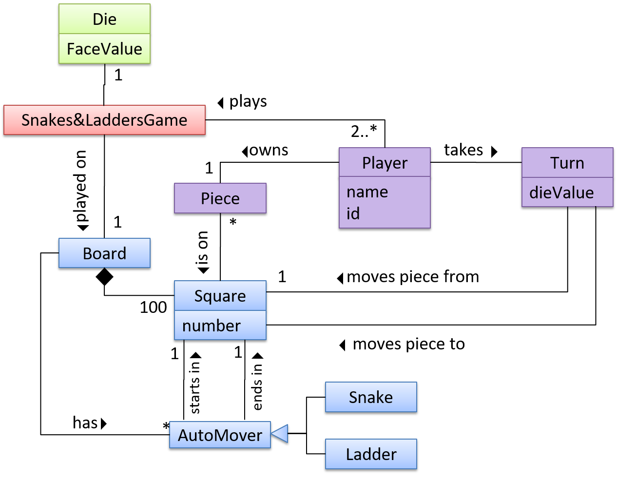
CCDs do not contain solution-specific classes (i.e. classes that are used in the solution domain but do not exist in the problem domain). For example, a class called DatabaseConnection could appear in a class diagram but not usually in a CCD because DatabaseConnection is something related to a software solution but not an entity in the problem domain.

CCDs represents the class structure of the problem domain and not their behavior, just like class diagrams. To show behavior, use other diagrams such as sequence diagrams.

CCD notation is a subset of the class diagram notation (omits methods and navigability).

Modeling behaviors

Activity Diagrams - Basic

Software projects often involve workflows. Workflows define the

flow in which a process or a set of tasks is executed. Understanding such workflows is important for the success of the software project.

Some examples in which a certain workflow is relevant to software project:

A software that automates the work of an insurance company needs to take into account the workflow of processing an insurance claim.

The algorithm of a piece of code represents the workflow (i.e. the execution flow) of the code.

Contents related to UML diagrams in the panels given below belong to a different chapter (i.e., the chapter dedicated to UML); they have been embedded here for convenience.

UML Activity Diagrams → Introduction → What

UML  activity diagrams (AD) can model workflows.  Flow charts are another type of diagram that can model workflows. Activity diagrams are the UML equivalent of flow charts.

An example activity diagram:

[source:wikipeida]


UML Activity Diagrams → Basic Notation → Linear Paths

An activity diagram (AD) captures an activity through the actions and control flows that make up the activity.

  • An action is a single step in an activity. It is shown as a rectangle with rounded corners.
  • A control flow shows the flow of control from one action to the next. It is shown by drawing a line with an arrow-head to show the direction of the flow.

Note the slight difference between the start node and the end node which represent the start and the end of the activity, respectively.

This activity diagram shows the action sequence of the activity a passenger rides the bus:


Exercises:

Which activity diagrams are correct?


UML Activity Diagrams → Basic Notation → Alternate Paths

A branch node shows the start of alternate paths. Each control flow exiting a branch node has a guard condition: a boolean condition that should be true for execution to take that path. Exactly one of the guard conditions should be true at any given branch node.

A merge node shows the end of alternate paths.

Both branch nodes and merge nodes are diamond shapes. Guard conditions must be in square brackets.

The AD below shows alternate paths involved in the workflow of the activity shop for product:

Some acceptable simplifications (by convention):

  • Omitting the merge node if it doesn't cause any ambiguities.
  • Multiple arrows can start from the same corner of a branch node.
  • Omitting the [Else] condition.

The AD below illustrates the simplifications mentioned above:


Exercises:

Which activity diagrams are correct?


UML Activity Diagrams → Basic Notation → Parallel Paths

Fork nodes indicate the start of

concurrent
flows of control.

Join nodes indicate the end of parallel paths.

Both have the same notation: a bar.

In a

set of parallel paths
, execution along all parallel paths should be complete before the execution can start on the outgoing control flow of the join.

In this activity diagram (from an online shop website) the actions User browses products and System records browsing data happen in parallel. Both of them need to finish before the log out action can take place.


Exercises:

Which activity diagrams are correct?


Which sequence of actions are supported?


Activity Diagrams - Intermediate

UML Activity Diagrams → Intermediate Notation → Rakes

The rake notation is used to indicate that a part of the activity is given as a separate diagram.

Here is the AD for a game of ‘Snakes and Ladders’.

The rake symbol (in the Move piece action above) is used to show that the action is described in another subsidiary activity diagram elsewhere. That diagram is given below.


UML Activity Diagrams → Intermediate Notation → Swim Lanes

It is possible to partition an activity diagram to show who is doing which action. Such partitioned activity diagrams are sometime called swimlane diagrams.

A simple example of a swimlane diagram:


Sequence Diagrams - Basic

Sequence diagrams model the interactions between various entities in a system, in a specific scenario. Modelling such scenarios is useful, for example, to verify the design of the internal interactions is able to provide the expected outcomes.

Some examples where a sequence diagram can be used:

To model how components of a system interact with each other to respond to a user action.

To model how objects inside a component interact with each other to respond to a method call it received from another component.

Contents related to UML diagrams in the panels given below belong to a different chapter (i.e., the chapter dedicated to UML); they have been embedded here for convenience.

UML Sequence Diagrams → Introduction

A UML sequence diagram captures the interactions between multiple entities for a given scenario.

Consider the code below.

class Machine {

    Unit producePrototype() {
        Unit prototype = new Unit();
        for (int i = 0; i < 5; i++) {
            prototype.stressTest();
        }
        return prototype;
    }
}

class Unit {

    public void stressTest() {

    }
}

Here is the sequence diagram to model the interactions for the method call producePrototype() on a Machine object.


UML Sequence Diagrams → Basic Notation

Notation:

This sequence diagram shows some interactions between a human user and the Text UI of a

CLI
Minesweeper game.

The player runs the newgame action on the TextUi object which results in the TextUi showing the minefield to the player. Then, the player runs the clear x y command; in response, the TextUi object shows the updated minefield.

The :TextUi in the above example denotes an unnamed instance of the class TextUi. If there were two instances of TextUi in the diagram, they can be distinguished by naming them e.g. TextUi1:TextUi and TextUi2:TextUi.

Arrows representing method calls should be solid arrows while those representing method returns should be dashed arrows.

Note that unlike in object diagrams, the class/object name is not underlined in sequence diagrams.

The arrowhead style depends on the type of method call. Arrows showing synchronous (i.e., the caller method is blocked from doing anything else until the called method returns) should use filled arrowheads (e.g., ). Most method calls (e.g., normal Java method calls) are synchronous. Asynchronous method calls (i.e., the caller method does not have to wait till the called method returns) are shown using lined arrowheads (e.g., ). As the latter is out of scope for this textbook, all sequence diagram arrow heads you encournter in this textbook will be of the first type.

[Common notation error] Activation bar too long: The activation bar of a method cannot start before the method call arrives and a method cannot remain active after the method has returned. In the two sequence diagrams below, the one on the left commits this error because the activation bar starts before the method Foo#xyz() is called and remains active after the method returns.

[Common notation error] Broken activation bar: The activation bar should remain unbroken while the method is being executed, from the point the method is called until the method returns. In the two sequence diagrams below, the one on the left commits this error because the activation bar for the method Foo#abc() is broken in the middle.


UML Sequence Diagrams → Loops

Notation:

The Player calls the mark x,y command or clear x y command repeatedly until the game is won or lost.


UML Sequence Diagrams → Object Creation

Notation:

  • The arrow that represents the constructor arrives at the side of the box representing the instance.
  • The activation bar represents the period the constructor is active.

The Logic object creates a Minefield object.


UML Sequence Diagrams → Minimal Notation

To reduce clutter, optional elements (e.g, activation bars, return arrows) may be omitted if the omission does not result in ambiguities or loss of

relevant information
. Informal operation descriptions such as those given in the example below can be used, if more precise details are not required for the task at hand.

A minimal sequence diagram

If method parameters don't matter to the purpose of the sequence diagram, you can omit them using ... e.g., use foo(...) instead of foo(int size, double weight).


Sequence Diagrams - Intermediate

UML Sequence Diagrams → Object Deletion

UML uses an X at the end of the lifeline of an object to show its deletion.

Notation:

Note how the below diagram shows the deletion of the Minefield object.

Although languages such as Java do not support a delete operation (because they use automatic memory management), you can use the object deletion notation to indicate the point at which the object becomes ready to be garbage-collected (i.e., the point at which it ceases to be referenced).

Note how d lifeline ends with an X to show that it is 'deleted' (i.e., ready to be garbage collected) after the cook() method returns.

class Chef {
    void cook() {
        Dish d = new Dish();
    }
}


UML Sequence Diagrams → Self-Invocation

UML can show a method of an object calling another of its own methods.

Notation:

The markCellAt(...) method of a Logic object is calling its own updateState(...) method.

In this variation, the Book#write() method is calling the Chapter#getText() method which in turn does a call back by calling the getAuthor() method of the calling object.

'Unroll' chained/compound method calls before drawing sequence diagram. Consider the Java statement new Book().add(new Chapter());. How do we show it as a sequence diagram? First, 'unroll' it into a simpler series of statements, which can then be drawn as a sequence diagram easily. For example, that statement is equivalent to the following:

Book b = new Book();
Chapter c = new Chapter();
b.add(c);

UML Sequence Diagrams → Alternative Paths

UML uses alt frames to indicate alternative paths.

Notation:

Minefield calls the Cell#setMine method if the cell is supposed to be a mined cell, and calls the Cell:setMineCount(...) method otherwise.

No more than one alternative partitions be executed in an alt frame. That is, it is acceptable for none of the alternative partitions to be executed but it is not acceptable for multiple partitions to be executed.


UML Sequence Diagrams → Optional Paths

UML uses opt frames to indicate optional paths.

Notation:

Logic#markCellAt(...) calls Timer#start() only if it is the first move of the player.


UML Sequence Diagrams → Calls to Static Methods

Method calls to static (i.e., class-level) methods are received by the class itself, not an instance of that class. You can use <<class>> to show that a participant is the class itself.

In this example, m calls the static method Person.getMaxAge() and also the setAge() method of a Person object p.

Here is the Person class, for reference:


Sequence Diagrams - Advanced

UML: Sequence Diagrams: Parallel Paths

UML uses par frames to indicate parallel paths.

Notation:

Logic is calling methods CloudServer#poll() and LocalData#poll() in parallel.

If you show parallel paths in a sequence diagram, the corresponding Java implementation is likely to be multi-threaded because a normal Java program cannot do multiple things at the same time.


UML: Sequence Diagrams: Reference Frames

UML uses ref frame to allow a segment of the interaction to be omitted and shown as a separate sequence diagram. Reference frames help you to break complicated sequence diagrams into multiple parts or simply to omit details you are not interested in showing.

Notation:

The details of the get minefield appearance interactions have been omitted from the diagram.

Those details are shown in a separate sequence diagram given below.


Use Case Diagrams

Use case diagrams model the mapping between features of a system and its user roles i.e., which user roles can perform which tasks using the software.

A simple use case diagram:

Modeling a solution

Introduction

You can use models to analyze and design software before you start coding.

Suppose you are planning to implement a simple minesweeper game that has a text based UI and a GUI. Given below is a possible OOP design for the game.

Before jumping into coding, you may want to find out things such as,

  • Is this class structure able to produce the behavior you want?
  • What API should each class have?
  • Do you need more classes?

To answer these questions, you can analyze how the objects of these classes will interact with each other to produce the behavior you want.

Basic

As mentioned in [Design → Modeling → Modeling a Solution → Introduction], this is the Minesweeper design you have come up with so far. Our objective is to analyze, evaluate, and refine that design.

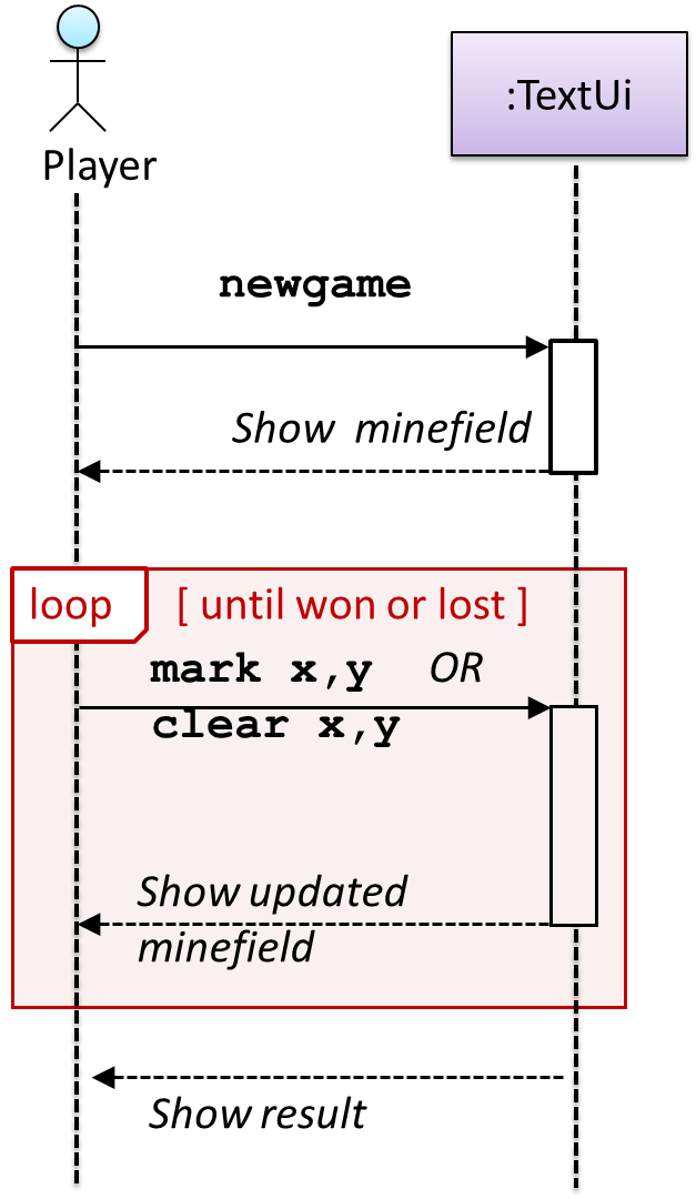
Let us start by modeling a sample interaction between the person playing the game and the TextUi object.

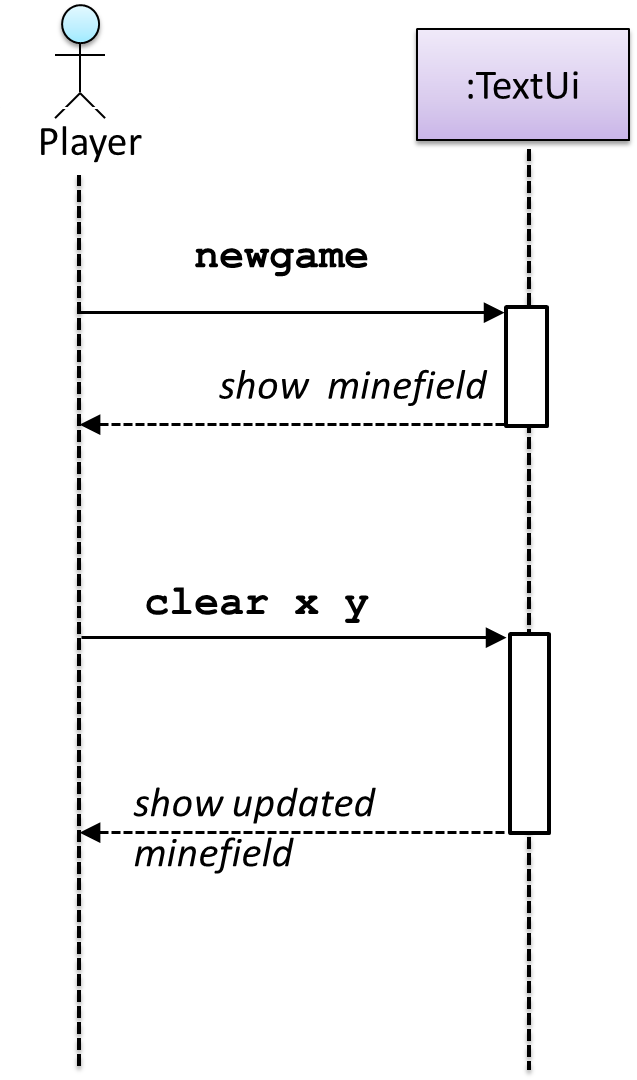
newgame and clear x y represent commands typed by the Player on the TextUi.

How does the TextUi object carry out the requests it has received from the player? It would need to interact with other objects of the system. Because the Logic class is the one that controls the game logic, the TextUi needs to collaborate with Logic to fulfill the newgame request. Let us extend the model to capture that interaction.

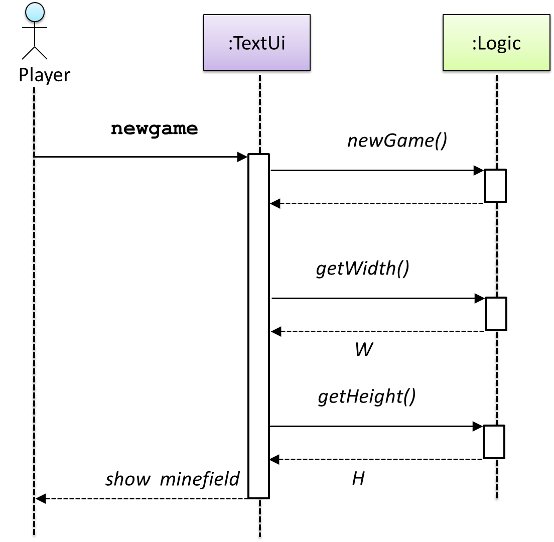
W = Width of the minefield; H = Height of the minefield

The above diagram assumes that W and H are the only information TextUi requires to display the minefield to the Player. Note that there could be other ways of doing this.

The Logic methods you conceptualized in our modeling so far are:

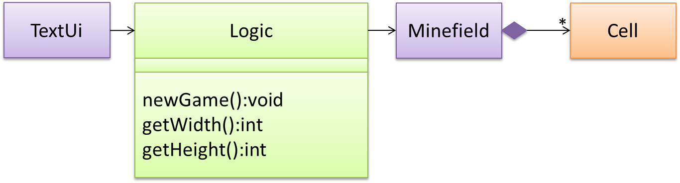
Now, let us look at what other objects and interactions are needed to support the newGame() operation. It is likely that a new Minefield object is created when the newGame() method is called.

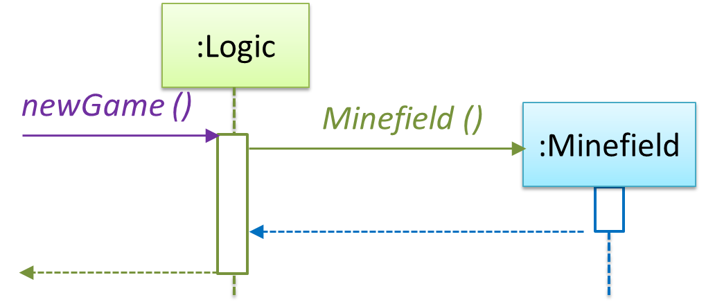
Note that the behavior of the Minefield constructor has been abstracted away. It can be designed at a later stage.

Given below are the interactions between the player and the TextUi for the whole game.

Note that

a similar technique
can be used when discovering/defining the architecture-level APIs.

Defining the architecture-level APIs for a small Tic-Tac-Toe game: